
Geometric Design Lab- Lab 02
Leg Centerline and Lanes using MicroStation
Copyright © 2009 by Dr. Thomas W. Rioux
Students taking this course may print one copy of this document for their
personal class use.
Objective: Learn the basics of MicroStation required to operate
GEOPAK by drawing a simple leg centerline and lanes.
Activity: Start MicroStation and create a 2D design file "Z:\MicroStation\lab_02.dgn" using the seed file "Z:\MicroStation\train2d.dgn" ; Use MicroStation to Draw a Leg Centerline; Use MicroStation to copy the centerline 12 feet parallel both above and below the centerline for lane edges; Change the lane edge attributes to color green (color=2) and solid style (style=0); Place a landscape oriented rectangle centered around the roadway in 8.5" by 11" proportion (2070 feet by 1583 feet); Place the title "Lab Assignment 02" centered at the top and your name, class name, and assignment due date in the lower right at a text height and width of 75 feet; Compress the MicroStation design file and Save the MicroStation design file settings; Select the black and white laser printer as the default printer; Place a fence around the rectangle and print the drawing; Exit MicroStation; and Reboot the computer.
Background: MicroStation is a Computer Aided Drafting (CAD) software package. GEOPAK is an MDL application that runs on MicroStation. Some knowledge of MicroStation is required to operate GEOPAK. Intersection analysis begins by defining the geometry of the intersection. A circular fillet is an arc of a circle that is tangent to two intersecting lines.
A. Start MicroStation and create a 2D design file
"Z:\MicroStation\lab_02.dgn" using the seed file "Z:\MicroStation\train2d.dgn".
B. Use MicroStation to Draw a Leg Centerline.
B.1. Set the element attributes.
B.1.a. Select the Active Level icon (leftmost icon) from the MicroStation Primary Tools menu at the top and choose Level 1 (level=Level 1).
B.1.b. Select the Active Color icon (next icon to the right) from the MicroStation Primary Tools menu at the top and choose the yellow color (color=4).
B.1.c. Select the Active Style icon (next icon to the right) from the MicroStation Primary Tools menu at the top and choose dash-dot style (style=4).
B.1.d. Select the Active Weight icon (next icon to the right) from the MicroStation Primary Tools menu at the top and choose weight 0 (weight=0).
B.2. Place leg centerline.
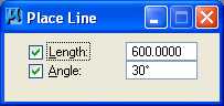
B.2.a. Place a 600 foot line at 30 degrees. From the MicroStation Main Tool menu, select the Linear Elements palette (row 2 right icon) and open it as a tool box in the MicroStation View 1 window.

B.2.b. From the Linear Elements palette, choose the Place Line icon (2nd from left on
the top row)  . From the Place Line
dialog box, select Length to be active (a check mark will appear), enter a
value of 600 feet (enter the tab character to set the number), select Angle
to be active (a check mark will appear), and enter a value of 30 degrees (enter
the tab character to set the number).
. From the Place Line
dialog box, select Length to be active (a check mark will appear), enter a
value of 600 feet (enter the tab character to set the number), select Angle
to be active (a check mark will appear), and enter a value of 30 degrees (enter
the tab character to set the number).
B.2.c. In the MicroStation Key-in field, enter "xy=5000,5000" plus a carriage return or the Enter key. This entry tells MicroStation that the line should start at an x-coordinate of 5000 feet and y-coordinate of 5000 feet.

B.2.d. In Window 1, press the Fit View icon (the 5th icon from the left)
 ; the line should be visible.

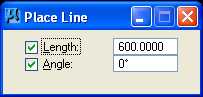
B.2.e. Place a 600 foot line at 0 degrees. In the
MicroStation window, choose Settings ->
Snaps. If Keypoint
does not have a check mark to its left then select Keypoint. In the
Inform Message field,
 should be displayed. From the Place
Line dialog box, select Length to be active, enter a value of 600
feet, select Angle to be active, and enter a value of 0 degrees.
should be displayed. From the Place
Line dialog box, select Length to be active, enter a value of 600
feet, select Angle to be active, and enter a value of 0 degrees.
B.2.f. Move the cursor in Window 1 near the top-right end of the previously placed line
and press the Tentative button. In the Status Message field,
"5519.6152, 5300.0000" should be displayed, a larger cursor should be positioned
on the top-right end of the previously placed line, and the previously placed line should
be highlighted in magenta (if this did not occur, choose
Workspace -> Button Assignments and set the tentative button to the middle button and try
again). Now press the Data button to accept this tentative
point. In Window 1, press the Fit View icon
; both lines should be visible.

B.2.g. Place a 600 foot line at 30 degrees. From the Place Line dialog box, select Length to be active, enter a value of 600 feet, select Angle to be active, and enter a value of 30 degrees.
B.2.h. Move the cursor in Window 1 near the top-right end of the previously placed line
and press the Tentative button. In the Status Message field,
"6119.6152, 5300.0000" should be displayed, a larger cursor should be positioned
on the top-right end of the previously placed line, and the previously placed line should
be highlighted in magenta. Now press the Data
button to accept this tentative point. In Window 1, press the Fit View
icon ; all three lines should be visible.
Close the Linear Elements palette by selecting the "X" in the upper right
corner.

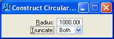
B.2.i. Place a 1000 foot radius fillet with truncate between the lines 1 and 2 and lines 2 and 3. From the MicroStation Main Tool menu, select the Modify palette (bottom row right icon) and open it as a tool box in the MicroStation View 1 window.

B.2.j. From the Modify palette, choose the Construct Circular Fillet icon (next to the
last icon)  . From the
Construct Circular Fillet dialog box, enter a Radius of 1000 feet and set
the Truncate option to Both.
. From the
Construct Circular Fillet dialog box, enter a Radius of 1000 feet and set
the Truncate option to Both.
B.2.k. Move the cursor over the 1st line and press the Data button
(MicroStation will highlight the 1st line); then move the cursor over the 2nd line
and press the Data button (MicroStation will highlight the 2nd line and construct
and highlight a 1000 foot circular fillet); and finally press the Data button anywhere
to accept the fillet. Move the cursor over the 2nd line and press the Data
button (MicroStation will highlight the 2nd line); then move the cursor over the 3rd
line and press the Data button (MicroStation will highlight the 3rd line and
construct and highlight a 1000 foot circular fillet); and finally press the Data
button anywhere to accept the fillet. In Window 1, press the Update
View icon  ; all three lines and both arcs
of a circle should be visible. Close the Modify palette by selecting
the "X" in the upper right corner.
; all three lines and both arcs
of a circle should be visible. Close the Modify palette by selecting
the "X" in the upper right corner.

C. Use MicroStation to copy the centerline 12 feet parallel both above and below the centerline for lane edges.
C.1. From the MicroStation tool palette, select the Manipulate palette (next to the bottom row right icon) and open it as a tool box in the MicroStation View 1 window.
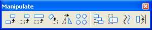
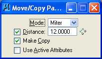
C.2. From the Manipulate palette, choose the Move Parallel icon (3rd icon from the
left)  . From the
Move/Copy Parallel
dialog box, select Mode: Miter, select Distance to be active (a
check mark will appear) and enter a
value of 12 feet, select Make Copy to be active (a
check mark will
appear).
. From the
Move/Copy Parallel
dialog box, select Mode: Miter, select Distance to be active (a
check mark will appear) and enter a
value of 12 feet, select Make Copy to be active (a
check mark will
appear).
C.3. Move the cursor over the 1st line and press the Data button (MicroStation will highlight the line), then move the cursor above the 1st line and press the Data button (MicroStation will copy the 1st line 12 feet parallel and above the 1st line), then move the cursor below the 1st line and press the Data button (MicroStation will copy the 1st line 12 feet parallel and below the 1st line), and finally enter a Reset button (right button).
C.4. Repeat Step C.3 for the 1st arc, the 2nd line, the 2nd arc, and the 3rd line; then close the Manipulate palette by selecting the "X" in the upper right corner.

D. Change the lane edge attributes to color green (color=2) and solid style (style=0).
D.1. From the MicroStation tool palette, choose the Change Attributes palette (next to the bottom row left icon) and open it as a tool box in the MicroStation View 1 window.
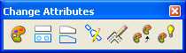
D.2. From the Change Attributes palette, choose the Change Element Attributes icon
(leftmost icon)  . From the
Change Element Attributes dialog box, select Color to be active (a check
mark
will appear) and choose the green color (color=2),
select Style to be active (a check mark will appear) and select solid
(style=0), and make sure that Use Active
Attributes, Level, Weight, and Class are not active.
. From the
Change Element Attributes dialog box, select Color to be active (a check
mark
will appear) and choose the green color (color=2),
select Style to be active (a check mark will appear) and select solid
(style=0), and make sure that Use Active
Attributes, Level, Weight, and Class are not active.

D.3. Move the cursor over the 1st line copied parallel 12 feet above and press the Data button (MicroStation will highlight the line) then move the cursor over the 1st line copied parallel 12 feet below and press the Data button (MicroStation will change the attributes of the previously selected line and highlight the newly selected line).
D.4. Repeat Step D.3 for all other arcs and lines except the centerline elements and finally press a Data button anywhere to accept the last element; then close the Change Attributes palette by selecting the "X" in the upper right corner.

E. Place a landscape oriented rectangle centered around the roadway in 8.5" by 11" proportion (2070 feet by 1583 feet).
E.1. From the MicroStation tool palette, choose the Polygons palette (3rd row right icon) and open it as a tool box in the MicroStation View 1 window.
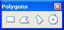
E.2. From the Polygons palette, choose the Place Block icon (leftmost)
 . From the Place Block dialog box,
choose Method = Orthogonal, Area = Solid, and Fill Type = None.
Select the Active Color icon (leftmost icon) from the MicroStation Primary Tools
menu at the top and choose the white color (color=0);
this will set Fill Color = 0 in the Place Block dialog box. Select the
Active Style icon (3rd icon from the left) from the MicroStation Primary Tools
menu at the top and choose solid style (style=0).
. From the Place Block dialog box,
choose Method = Orthogonal, Area = Solid, and Fill Type = None.
Select the Active Color icon (leftmost icon) from the MicroStation Primary Tools
menu at the top and choose the white color (color=0);
this will set Fill Color = 0 in the Place Block dialog box. Select the
Active Style icon (3rd icon from the left) from the MicroStation Primary Tools
menu at the top and choose solid style (style=0).

E.3. Move the cursor to the left edge of the leftmost line and enter a Data
button (left button), then in the MicroStation Key-in field enter "dx=2070,1583"
to place a data point 2070 feet in the x direction and 1583 feet in the y direction from
the current data point and press the carriage return or Enter key; then close
the Polygons palette by selecting the "X" in the upper right corner; and finally
choose the Fit View icon .

E.4. From the MicroStation tool palette, choose the Manipulate palette (next to the bottom row right icon) and open it as a tool box in the MicroStation View 1 window.
E.5. From the Manipulate palette, choose the Move icon (2nd icon from the left)
 . Select the rectangle placed in Step
E.3 and move it until the road is approximately centered; then close the Manipulate
palette by selecting the "X" in the upper right corner; and finally choose the Fit
View icon .
. Select the rectangle placed in Step
E.3 and move it until the road is approximately centered; then close the Manipulate
palette by selecting the "X" in the upper right corner; and finally choose the Fit
View icon .

F. Place the title "Lab Assignment 02" centered at the top and your name, class name, and assignment due date in the lower right at a text height and width of 75 feet.
F.1. From the MicroStation tool palette, choose the Text palette (5th row right icon) and open it as a tool box in the MicroStation View 1 window.
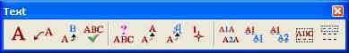
F.2. From the Text
palette, choose the Place Text icon (leftmost icon)
 .
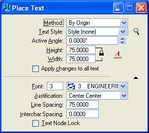
In the Place Text dialog box,
set Method = By Origin, Text Style = none,
Active Angle = 0, Height =
75
feet, Width = 75 feet, set Font = 3 (Font=ENGINEERING),
Justification = Center Center, Line Spacing =
75 feet, and
Interchar Spacing = 0.
.
In the Place Text dialog box,
set Method = By Origin, Text Style = none,
Active Angle = 0, Height =
75
feet, Width = 75 feet, set Font = 3 (Font=ENGINEERING),
Justification = Center Center, Line Spacing =
75 feet, and
Interchar Spacing = 0.
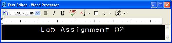
F.3. In the Text Editor - Word Processor dialog box, enter "Lab Assignment 02".
F.4. Move the cursor until the text is centered near the top of the rectangle, and enter a Data button (left button).

F.5. From the Text Editor - Word Processor dialog box, enter your name; the carriage return or Enter key; "Geometric Design Lab Spring 2011Geometric Design Lab"; the carriage return or Enter key; and the assignment due date in day-month-year (03-Feb-2010) notation.

F.6. Move the cursor until the text is near the bottom right of the rectangle, enter a Data button (left button), close the Text Editor - Word Processor dialog box by selecting the "X" in the upper right corner, and finally close the Text palette by selecting the "X" in the upper right corner.

G. Compress the MicroStation design file and Save the MicroStation design file settings.
G.1. In the MicroStation dialog box, choose File -> Compress -> Design.
G.2. In the MicroStation dialog box, choose File -> Save Settings.
H. Select the black and white laser printer as the default printer.
H.1. From the Windows Start Menu in the lower left corner of the screen, choose Start -> Printers and Faxes.
H.2. In the Printers and Faxes dialog box, Select ENGR-SC2-Laser-2, choose File -> Set as Default Printer, then close the dialog box by pressing the red "X" in the upper right corner of the dialog box.

I. Place a fence around the rectangle and print the drawing.
I.1. From the MicroStation tool palette, choose the Fence palette (top row right icon) and open it as a tool box in the MicroStation View 1 window.

I.2. From the Fence palette, choose the Place icon (leftmost icon)
 . From the Place Fence dialog box, choose Fence
Type = Element and Fence Mode = Inside; then select the rectangle
enclosing the entire design placed in Step E, and press the Data
button (left button); and
finally close the Fence palette by selecting the "X" in the upper right
corner.
. From the Place Fence dialog box, choose Fence
Type = Element and Fence Mode = Inside; then select the rectangle
enclosing the entire design placed in Step E, and press the Data
button (left button); and
finally close the Fence palette by selecting the "X" in the upper right
corner.

I.3. From the MicroStation window, choose File -> Print. If the Print dialog box does not look like the image below because it is narrower, press the right-arrow Show Preview button below the "X" in the upper right corner. If the Print dialog box does not look like the image below because it is shorter, press the down-arrow Show Details button in the lower right corner.

I.4. From the Print dialog box in the General Settings group, choose Area = Fence, Copies = 1, and Color = Monochrome.
I.5. From the Print dialog box in the
Printer and Paper Size group, press the Configure
Windows Printer icon
 immediately to the right of the Select Printer Driver icon
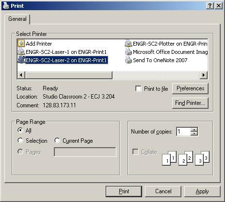
 . In the Print
dialog box, in the Select Printer group choose ENGR-SC2-Laser-2, press the Apply push button,
and close the Print dialog box by
selecting the "X" in the upper right corner.
. In the Print
dialog box, in the Select Printer group choose ENGR-SC2-Laser-2, press the Apply push button,
and close the Print dialog box by
selecting the "X" in the upper right corner.
I.6. From the Print dialog box in the Printer and Paper Size group, choose Paper = Letter, Landscape, and deselect Full Sheet. From the Print dialog box in the Print Scale and Position group, set Scale To 200 ft (dgn) to 1 in. (paper).

I.7. From the Print dialog box, choose Settings -> Print Attributes.... In the Print Attributes dialog box, set Print Border to on, set Fence Boundary to off, and press the OK push button.

I.8. From the Print dialog box, choose File -> Print and in the Print dialog box choose Print.
I.9. Get your print from the printer and check your print. Close the Print dialog box by selecting the "X" in the upper right corner.
Leg Centerline and Lanes Print
J. Exit MicroStation.
J.1. In the MicroStation dialog box, choose File -> Compress -> Design.
J.2. In the MicroStation dialog box, choose File -> Save Settings.
J.3. In the MicroStation dialog box, choose File -> Exit.
K. Reboot the computer.
Geometric Design Lab Spring 2011 web page
Latest Update: 11 Feb 2011 02:43 PM