Geometric Design Lab - Lab 08
Define a Spiral Curve using GEOPAK
Copyright © 2009 by Dr. Thomas W. Rioux
Students taking this course may print one copy of this document for their personal class
use.
Objective: Learn spiral curve design using GEOPAK.
Activity: Start MicroStation and create a 2D design file "Z:\MicroStation\lab_08.dgn" using the seed file "Z:\MicroStation\train2d.dgn"; Start GEOPAK and set the standard GEOPAK user preferences and the COGO preferences for this class; Create a GEOPAK Project named lab_08 using Job Number 08 with Subject of "Spiral Curve" and set Coordinate Geometry for Temporary Visualization; Store the points for the centerline; Store the horizontal spiral from tangents; Create the centerline chain; Draw the centerline chain and station the centerline chain; Attach "Z:\MicroStation\lab_07.dgn" to "Z:\MicroStation\lab_08.dgn" as a reference file; Measure and dimension the distance between the circular arc chain from Lab Assignment 07 and the spiral chain from this lab; Place a landscape oriented rectangle centered around the drawings in 8.5" by 11" proportion; Place the title "Lab Assignment 08" at the top center and your name, class name, and assignment due date in the bottom center; Place a fence from the rectangle and plot the drawing; Exit MicroStation; and Reboot the computer.
Background: Spiral curves are desirable to accomplish superelevation runoff and provide a gradual change in direction between the tangent and a circular curve. When spiral curves are introduced at each end of a circular curve, the circular curve is displaced inward from each tangent and its arc length and central angle are reduced to accommodate the spirals. GEOPAK computes the location of spirals of chosen length and develops the elements of an alignment chain comprising: tangent, spiral, circular arc, spiral, and tangent. AASHTO suggests that the length of spiral should be the same as the length of superelevation runoff and that the end of the spiral at the tangent (TS or ST) should be located at the station where adverse crown has been removed (end of tangent runout).
A. Start MicroStation and create
a 2D design file "Z:\MicroStation\lab_08.dgn" using the seed file "Z:\MicroStation\train2d.dgn".
B. Start GEOPAK and set the standard GEOPAK user preferences and the COGO preferences for this class.
C. Create a GEOPAK Project named lab_08 using Job Number 08 with Subject of "Spiral Curve" and set Coordinate Geometry for Temporary Visualization.
D. Store the points for the centerline.
D.1. Store Point Number 1 at an X of 5000 and a Y of 5000.
D.2. Store Point Number 2 at a Bearing of N 90 E and a Distance of 1000 feet from Point Number 1.
D.3. Store Point Number 3 at a Bearing of S 45 E and a Distance of 1000 feet from Point Number 2.
D.4. Minimize the Coordinate Geometry dialog box. In MicroStation Window 1, choose the Fit View icon. The 3 points should be visible.
E. Store the horizontal spiral from tangents.
E.1. Calculate the desired spiral length as the length required for both tangent runout and superelevation runoff using a 12 foot lane width, 30 mi/hr design speed, 8% maximum superelevation rate, and 1200 foot radius thus the desired spiral length would be the lane width (12 feet) times the change in superelevation rate (-2% to 3.6% gives 5.6%) (see Exhibit 3-23 on page 161 of the 2001 AASHTO Green Book) times the relative pavement edge profile slope (1:152 thus 152) (see Exhibit 3-27 on page 170 of the 2001 AASHTO Green Book) giving 12*0.056*152 = 102.144 feet rounded gives 102.14 feet.
E.2. In the Coordinate Geometry dialog box, choose Element -> Spiral -> Store.
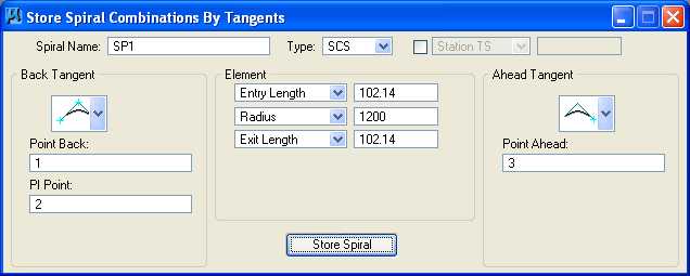
E.3. In the Store Spiral Combinations By Tangents dialog box, set Spiral Name to SP1, set Type to SCS, and set Station PI or Station TS to off.
E.4. In the Store Spiral Combinations
By Tangents dialog box, in the Back Tangent group, press the icon at the top and choose the
last icon
 ; Point
Back and PI Point are displayed
below the icon, set Point
Back to 1, and set
PI Point to 2.
; Point
Back and PI Point are displayed
below the icon, set Point
Back to 1, and set
PI Point to 2.
E.5. In the Store Spiral Combinations By Tangents dialog box, in the Element group, set Entry Length to 102.14 feet, set Radius to 1200 feet, and set Exit Length to 102.14 feet.
E.6. In the Store Spiral Combinations By Tangents dialog box, in
the Ahead Tangent group, press the icon at the top and choose
the middle icon
 ;
Point Ahead is displayed below the icon, and set
Point
Ahead to 3.
;
Point Ahead is displayed below the icon, and set
Point
Ahead to 3.
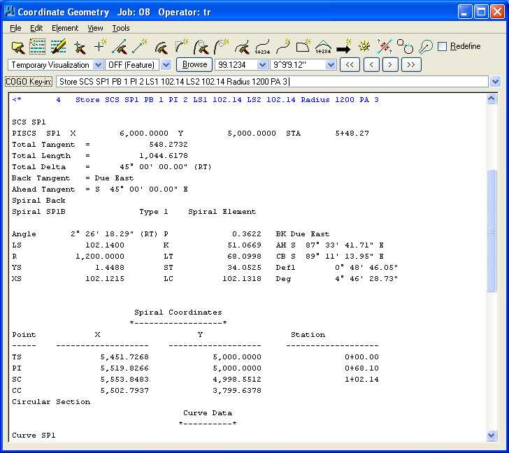
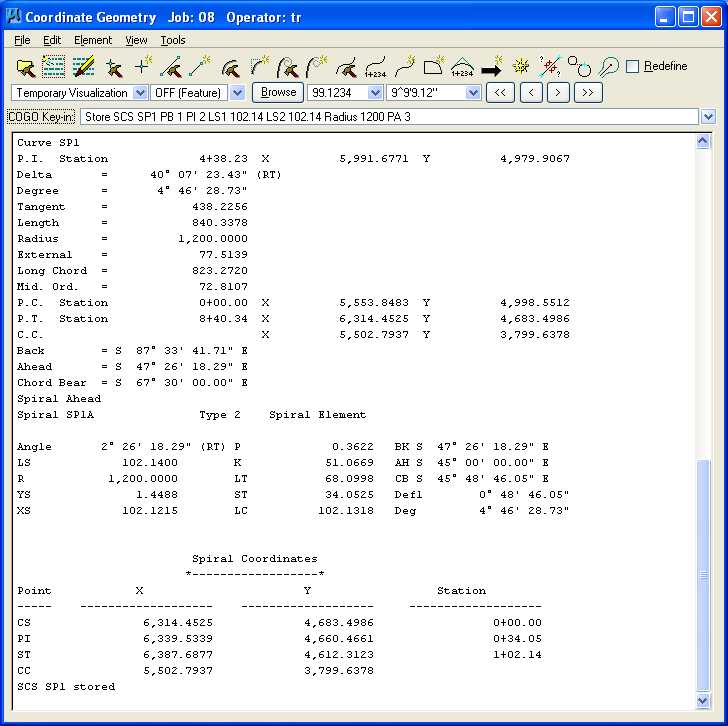
E.7. Press the Store Spiral button and close the Store Spiral Combinations By Tangents dialog box. The command issued to perform the operation (Store SCS SP1 PB 1 PI 2 LS1 102.14 LS2 102.14 Radius 1200 PA 3) is displayed in the upper part of the Coordinate Geometry dialog box while information about the spiral is listed in the lower part of the Coordinate Geometry dialog box. Notice that the 1st element is called a Spiral Back and named Spiral SP1B, the 2nd element is called a Circular Section and named Curve SP1, and the 3rd element is called a Spiral Ahead and named Spiral SP1A.
E.8. In MicroStation Window 1, choose the Fit View icon. The 3 points, horizontal circular curve, and spirals should be visible.
F. Create the centerline chain with a Chain Name of CH1, Begin at 0+00, the 1st segment is Point 1, the 2nd segment is Spiral SP1B (SP1B is SP1 Back from Point Back to the PI Point), the 3rd segment is Curve SP1, the 4th segment is Spiral SP1A (SP1A is SP1 Ahead from the PI Point to the Point Ahead), and the 5th segment is Point 3. Minimize the Coordinate Geometry dialog box. In MicroStation Window 1, choose the Fit View icon. The 3 points, horizontal circular curve, spirals, and chain should be visible.
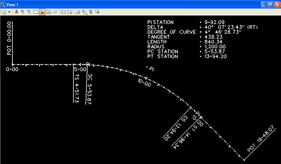
G. Draw the centerline chain and station the centerline chain.
G.1. Draw the centerline chain using the Design and Computation Manager using the Texas Department of Transportation (TxDOT) GEOPAK parameter file "Z:\MicroStation\txengd.ddb" selecting FEATURES then DRAFTING STANDARDS, then Alignments, then BL Baseline Horizontal Alignment, and finally Draw Plan & Profile for Job 08 setting Element Type to Chains, all options to off, and Label Scale to 200 for Chain CH1.
G.2. Draw the centerline curve data setting Element Type to Curves, Curve Data on, all other options to off, and Label Scale to 200 for Curve SP1.
G.3. Station the centerline chain setting Element Type to Stationing, Tick Marks to on, Tick Marks Stations to on, PC/PT/TS/CS/SC/ST Labels to on, PI Labels to on, Small Ticks to Ticks Right; Labels Right, Large Ticks to Ticks Both; Labels Right, Control Point Labels to As Per Preferences, and Label Scale to 200 for Chain CH1.
G.4. Close the Draw Plan & Profile dialog box and close the Design and Computation Manager dialog box.
G.5. In the Coordinate Geometry dialog box, choose Tools -> Clear Visualized Elements (Temporary) and File -> Exit.
G.6. Move the Curve Data so the PI is visible.
G.7. In MicroStation Window 1, choose the Fit View icon. The centerline chain and stationing should be visible.
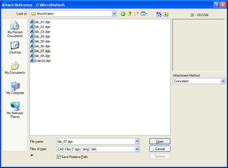
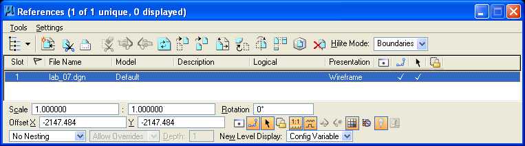
H. Attach "Z:\MicroStation\lab_07.dgn" to "Z:\MicroStation\lab_08.dgn" as a reference file.
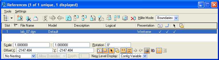
H.1. From the MicroStation dialog box, choose File -> Reference.
H.2. In the References dialog box, choose Tools -> Attach.
H.3. In the Attach Reference dialog box under Files of Type, choose CAD Files (*.dgn;*.dwg;*.dxf); under Look in, select Z:\MicroStation; in File name, choose lab_07.dgn; set Save Relative Path to on; under Attachment Method, select Coincident; and Press the Open push button. An Alert box may appear stating "Path not part of MS_RFDIR; press the OK push button.
H.4. In the References dialog box, set Display
to on (under
 ), set Snap to on
(under
), set Snap to on
(under
 ), and set Locate
to on (under
), and set Locate
to on (under
 ).
).
H.5. In the MicroStation Window 1, choose fit then in the Fit View dialog box set Files to All, then choose fit again.
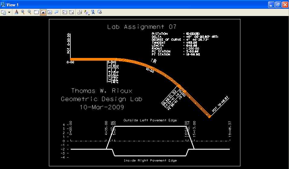
I. Measure and dimension the distance between the circular arc chain from Lab Assignment 07 and the spiral chain from this lab.
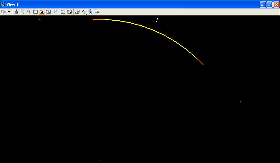
I.1. In MicroStation Window 1, choose the Zoom In icon. Move the cursor between the two chains at station 10+00 and press the Data button approximately 12 times until the station 10+00 line between the two chains is as large as possible.

I.2. From the MicroStation tool palette, choose the Measure palette (7th row left icon).
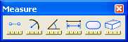
I.3. From the Measure palette, choose the Measure
Distance icon (leftmost icon)
 .
.
I.4. In the Measure Distance dialog box, set Distance to Between Points and set Mode to True. (Hint: you may want to use Intersection Snap)

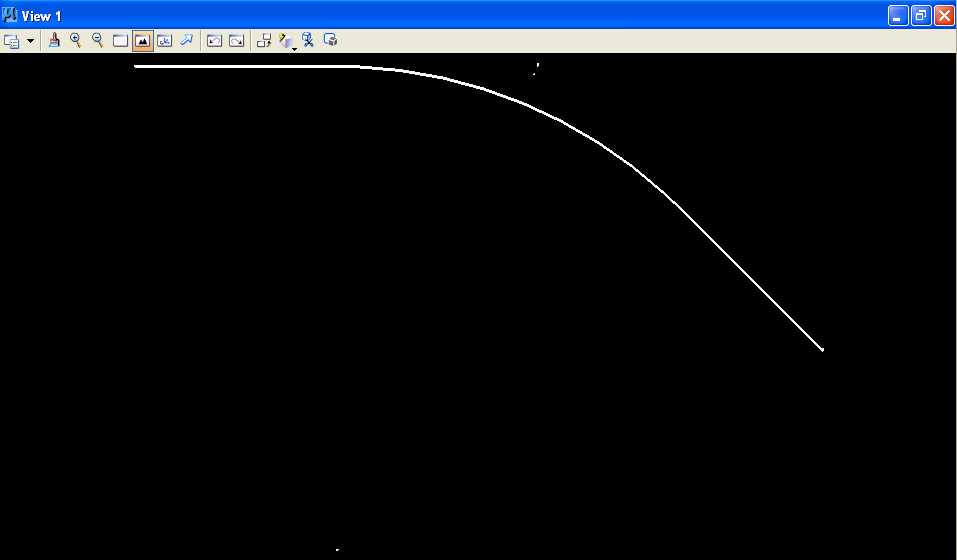
I.5. Move the cursor over the intersection of the station 10+00 line and the old chain (white dashed line very near the orange line) and press the Data button, move the cursor over the intersection of the station 10+00 line and the new chain (white dashed line below old line) and press the Data button, and save the distance rounded to 3 decimal places that is displayed in the Measure Distance dialog box Distance field.
I.6. Set the active the level to Level 1 (level=Level 1), color to green (color=2), the style to solid (style=0), and the weight to 0 (weight=0).
I.7. From the MicroStation tool palette, choose the Text palette (5th row right icon).
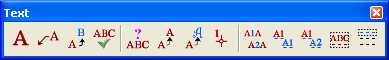
I.8. From the Text palette, choose the Place Note
icon (2nd icon from the left)
 .
.
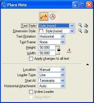
I.9. In the Place Note dialog box, press the
Place Note icon
![]() , set Type
Style to Style (none),
set Dimension Style to Style (none), set
Text Rotation to Horizontal, set Text Frame to None,
set Height to 50 feet, set Width to 50 feet, set Apply changes to all text to off,
set
Location to Manual, set Leader Type to Line, set
Start At to Terminator, set Horizontal
Attachment to Auto,
and set In Line Leader to off.
, set Type
Style to Style (none),
set Dimension Style to Style (none), set
Text Rotation to Horizontal, set Text Frame to None,
set Height to 50 feet, set Width to 50 feet, set Apply changes to all text to off,
set
Location to Manual, set Leader Type to Line, set
Start At to Terminator, set Horizontal
Attachment to Auto,
and set In Line Leader to off.
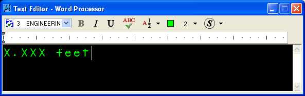
I.10. In the Text Editor - Word Processor dialog box, set Font to 3 (Font=ENGINEERING) and enter "X.XXX feet" where X.XXX is the value determined by the measure distance command from Step I.5.
I.11. Move the cursor between the intersection of the station 10+00 line and the old chain and the intersection of the station 10+00 line and the new chain and press the Data button.
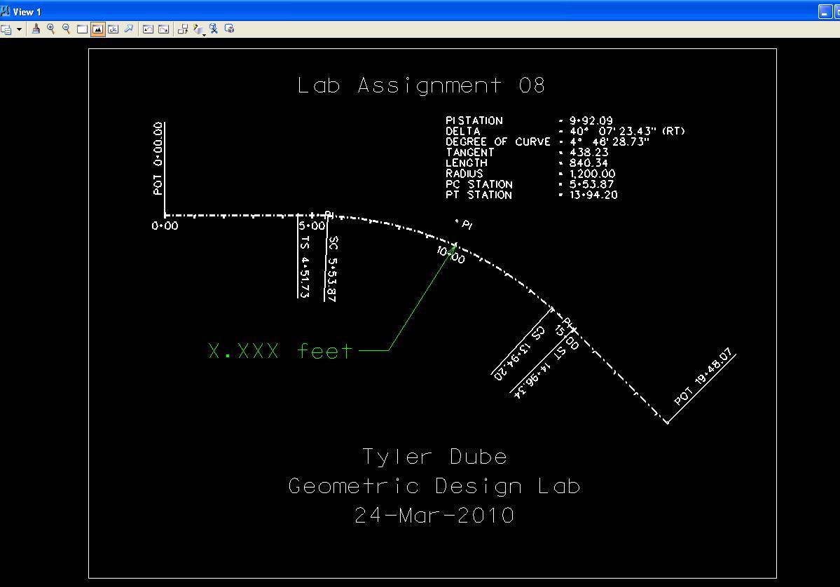
I.13. In MicroStation Window 1, choose the Fit View icon, press the Reset button, move the cursor to position the text as shown below, press the Data button to accept the position, and press the Reset button to end the Place Note command.
I.14. From the MicroStation dialog box, choose File -> Reference.
I.15. In the References dialog box for
Z:\MicroStation\lab_07.dgn, set Display
to off (under
)
and close the References dialog box.
J. Place a landscape oriented rectangle centered around the drawings in 8.5" by 11" proportion (2340 feet by 1800 feet) with level of Level 1 (level=Level 1), color of white (color=0), style of solid (style=0), and weight of 0 (weight=0).
K. Place the title "Lab Assignment 08" at the top center and your name, class name, and assignment due date in the bottom center using a text height, text width, and text line spacing of 50 feet with font of 3 (font=ENGINEERING), justification of Center Center, level of Level 1 (level=Level 1), color of white (color=0), style of solid (style=0), and weight of 0 (weight=0).
L. Place a fence from the rectangle placed in Step J and plot the drawing using ENGR-SC2-Laser-2 and options for Fence, Monochrome, Letter, Landscape, a Scale of 250 ft / in, and Settings -> Print Attributes -> Fence boundary off and Print border on.
Define a Spiral Curve using GEOPAK Plot
M. Exit MicroStation.
N. Reboot the computer.
Geometric Design Lab Spring 2011 web page
Latest Update: 11 Feb 2011 03:31 PM