Geometric Design Lab - Lab 11
Design Project Part 2
Design the Intersection Channelization of the Grade-Separated, Two-Quadrant, Partial
Cloverleaf A Interchange using MicroStation
Copyright © 2009 by Dr. Thomas W. Rioux
Students taking this course may print one copy of this document for their
personal class use.
Objective: Design the Intersection Channelization of the
Grade-Separated, Two-Quadrant, Partial Cloverleaf A Interchange using MicroStation.
Activity: Start MicroStation, open the 2D design file "Z:\MicroStation\lab_10.dgn", and Save As "Z:\MicroStation\lab_11.dgn"; Attach the cell file "design_project.cel"; Determine the location of the intersection of the ramps and Road 2000; Draw the 8-foot wide divisional island (preliminary); Design the southbound Road 2000 to westbound Entrance Ramp right turn; Design the northbound Road 2000 to westbound Entrance Ramp left turn; Design the eastbound Exit Ramp to northbound Road 2000 left turn; Design the eastbound Exit Ramp to southbound Road 2000 right turn; Complete the design of the divisional island; Set Level Display for Level 11, Level 12, Level 14, and Level 17 to on; Fit View 1 and plot the drawing; Exit MicroStation; Write the name of your team members on the plot; Complete Design Project Design Questions section 2; and Reboot the computer.
Background: This laboratory comprises Design Project Part 2 - Design the Intersection Channelization of the Grade-Separated, Two-Quadrant, Partial Cloverleaf A Interchange using MicroStation (see Design Project). You will use the features of MicroStation to design the intersection channelization where the Exit Ramp terminates and the Entrance Ramp begins at Road 2000. The intersection should accommodate WB-50 trucks. The angle between the ramps and the north part of Road 2000 should be 85 degrees. The entrance ramp and the exit ramp will have an 8 foot median at their closest points (edge of lane to edge of lane). The divisional island between the ramps should be 8 feet in width with a 1 foot radius circular end and a 15:1 taper section from the circular end to the divisional island edges. The maximum superelevation rate should be 8%. The right turn from the Exit Ramp eastbound to Road 2000 southbound should accommodate a design speed of 25 miles/hr. An asymmetric three-centered compound circular curve will be used for the Road 2000 southbound to the Entrance Ramp westbound lane edge. A symmetric five-centered compound circular curve will be used for the Exit Ramp eastbound to the Road 2000 southbound lane edge.
A. Start MicroStation, open the
2D design file "Z:\MicroStation\lab_10.dgn", and Save As "Z:\MicroStation\lab_11.dgn".
B. Attach the cell file "design_project.cel".
C. Determine the location of the intersection of the ramps and Road 2000.
C.1. Determine the minimum radius horizontal circular curve from Exhibit 3-15 in the 2004 AASHTO Green Book on page 147 for a design speed of 50 miles/hr and a maximum superelevation rate of 8 percent, double this rounded radius value to become a diameter, add approximately 200 feet (for tangent/taper sections and one-half the width of the Freeway), and round the distance to the next highest 5 feet if needed.
C.2. Ensure that there is adequate stopping sight distance for a traffic signal at this intersection after traveling over the crest curve and the sag curve. Determine the length, if any, of any at-grade section after the VPT of the southern sag curve of Road 2000 using Exhibit 3-1 in the 2004 AASHTO Green Book on page 112 for a design speed of 50 miles/hr. Add the distance from the centerline of the Freeway to the VPT of the southern sag curve for Road 2000 plus the length, if any, of any at-grade section after the VPT of the southern sag curve of Road 2000 plus approximately 15 feet for the distance from the stop line to the center of the intersection on Road 2000 and round the distance to the next highest 5 feet.
C.3 Determine the maximum value of the distance determined in Step C.1 and Step C.2.
D. Draw the 8-foot wide divisional island (preliminary).
D.1. Draw a centerline for the divisional island at the proper angle starting at the station defined by the distance from Step C.3 on the centerline of Road 2000 to the West for a distance of 500 feet with Level of Level 1, Color of 0 (white), Style of 4 (dash dot), and Weight of 0.
D.2. Copy the centerline from Step D.1 to create the inner edge of the lane (not the shoulder) and outer edge of the lane (not the shoulder) for the entrance and exit ramps and change the Style to 0 (Solid line).
D.3. Place a circle with radius of 1 feet centered at the intersection of the centerline from Step D.1 and the right shoulder of the southbound lane of Road 2000 (a green line) with Style of 0 (solid line).
D.4. Draw a 40 foot line tangent to the divisional island circle placed in Step D.3 that is a 15:1 taper from the Entrance/Exit Ramp centerline in the northwestern and southwestern direction and extend/shorten the western end of these lines with the edge of the divisional island.
D.5. Partial delete the circle placed in Step D.3 at the tangent points of the lines drawn in Step D.4 to create a circular arc and extend/shorten the circular arc (you may want to use Modify Arc Angle) and the lines drawn in Step D.4 to the points of tangency.
E. Design the southbound Road 2000 to westbound Entrance Ramp right turn.
E.1. Set Active Level to Level 10.
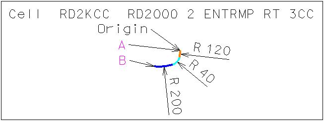
E.2. Choose cell RD2KCC for Placement. This cell is composed of three circular curves with radii of 120, 40, and 200 feet. These values come from Exhibit 9-20 in the 2004 AASHTO Green Book on page 589 for an Angle of Turn of 90 degrees, a Design Vehicle of WB-50, and the asymmetric three-centered compound curve section and from Exhibit 9-25 in the 2004 AASHTO Green Book on page 602.
E.3. Place the Active Cell with an Active Angle of 0, X Scale of 1, Y Scale of 1, True Scale set on, and Relative set on such that Point A of this cell is tangent to the right lane edge of the right southbound lane of Road 2000 (a red line) above the intersection and such that Point B of this cell is tangent to the northern lane edge of the Entrance Ramp created in Step D.2.
E.4. Extend/Shorten the eastern end of the northern lane edge of the Entrance Ramp to touch the southwestern end of the cell (Point B) placed in Step E.3.
E.5. Set Active Level to Level 11.
E.6. Choose cell RD2KRT for Placement. This cell is composed of a vehicle turn template for a WB-50 truck rotated for the southbound Road 2000 direction with a turn radius of 45 feet, a turn angle of 95 degrees, and a 2-foot clearance zone.
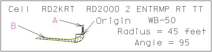
E.7. Place the Active Cell with an Active Angle of 0, X Scale of 1, Y Scale of 1, True Scale set on, and Relative set on such that Point A and Point B on the yellow clearance line of this cell are tangent to the critical points on Road 2000 and the Entrance Ramp or the cell placed in Step E.3 according to the criteria in the top paragraph on page 592 of the 2004 AASHTO Green Book. The outside front bumper clearance zone line may overlap the divisional island. The divisional island can be adjusted later in this assignment.
E.8. Review the clearance zones for the vehicle turn template and adjust the location of the 8-foot wide divisional island drawn in Step D if necessary.
F. Design the northbound Road 2000 to westbound Entrance Ramp left turn.
F.1. Set Active Level to Level 12 and set Level Display for Level 11 to off.
F.2. Choose cell RD2KLS for Placement. This cell is composed of a vehicle turn template for a WB-50 truck rotated for the northbound Road 2000 direction with a turn radius of 45 feet, a turn angle of 95 degrees, and a 2-foot clearance zone. This vehicle turn template is intentionally 10 degrees more than the 85 degree turn because many truck drivers execute this maneuver to make turns.
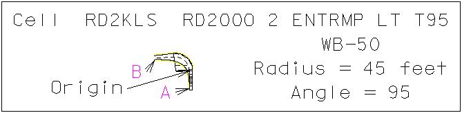
F.3. Place the Active Cell with an Active Angle of 0, X Scale of 1, Y Scale of 1, True Scale set on, and Relative set on such that Point A and Point B on the yellow clearance line of this cell are tangent to the critical points on Road 2000 and the divisional island circle placed in Step D.3 according to the criteria in the top paragraph on page 592 of the 2004 AASHTO Green Book. Notice that this 95-degree turn angle will not allow turning into the Entrance Ramp directly, but the driver can steer into the Entrance Ramp after making the 95-degree turn and staying within the lane edges.
F.4. Set Active Level to Level 13.
F.5. Choose cell RD2KLT for Placement. This cell is composed of a vehicle turn template for a WB-50 truck rotated for the northbound Road 2000 direction with a turn radius of 45 feet, a turn angle of 85 degrees, and a 2-foot clearance zone.
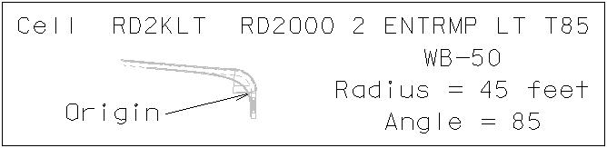
F.6. Place the Active Cell with an Active Angle of 0, X Scale of 1, Y Scale of 1, True Scale set on, and Relative set on such that the truck is in the same exact location as the truck placed in Step F.3 (Hint: use origin snap). The 85-degree turn angle does not allow a direct turn into the Entrance Ramp after clearing the divisional island nose.
F.7. Review the clearance zones for the vehicle turn templates and adjust the location of the 8-foot wide divisional island drawn in Step D if necessary.
G. Design the eastbound Exit Ramp to northbound Road 2000 left turn.
G.1. Set Active Level to Level 14 and set Level Display for Level 12 and Level 13 to off.
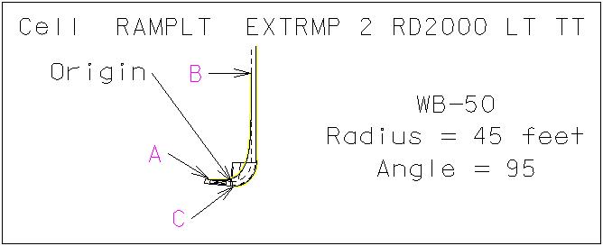
G.2. Choose cell RAMPLT for Placement. This cell is composed of a vehicle turn template for a WB-50 truck rotated for the eastbound Exit Ramp direction with a turn radius of 45 feet, a turn angle of 95 degrees, and a 2-foot clearance zone.
G.3. Place the Active Cell with an Active Angle of 0, X Scale of 1, Y Scale of 1, True Scale set on, and Relative set on such that Point A and Point B on the yellow clearance line of this cell are tangent to the critical points of the divisional island and Road 2000 right lane according to the criteria in the top paragraph on page 592 of the 2004 AASHTO Green Book. The southernmost lane edge may have to be extended to place the cell; if so, re-extend it to the taper section as per Step D.4.
G.4. Review the clearance zones for the vehicle turn template and adjust the location of the 8-foot wide divisional island drawn in Step D if necessary.
H. Design the eastbound Exit Ramp to southbound Road 2000 right turn.
H.1. Set Active Level to Level 15 and set Level Display for Level 14 to off.
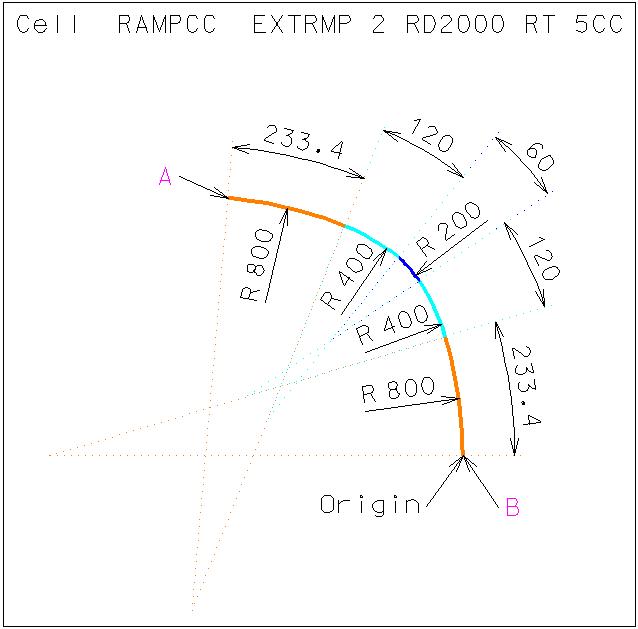
H.2. Choose cell RAMPCC for Placement. This cell is composed of five circular curves with radii of 800, 400, 200, 400, and 800 feet and with arc lengths of 233.4, 120, 60, 120, and 233.4 feet respectively. These values are derived from Exhibit 3-27 in the 2004 AASHTO Green Book on page 170 minimum for 8% maximum superelevation and a design speed of 25 mph, from Exhibit 3-24 in the 2004 AASHTO Green Book on page 165, and from Exhibit 3-32 in the 2004 AASHTO Green Book on page 181.
H.3. Place the Active Cell with an Active Angle of 0, X Scale of 1, Y Scale of 1, True Scale set on, and Relative set on such that Point A of this cell is tangent to the right lane edge of the right eastbound lane of the Exit Ramp placed in Step D.2 and such that Point B of this cell is tangent to the right lane edge of the right southbound lane of Road 2000 (a red line).
H.4. Partial Delete the right lane edge of the right eastbound lane of the Exit Ramp placed in Step D.2 at a location approximately in the center of the line and East of Point A in the cell placed in Step H.3.
H.5. Extend/Shorten the eastern end of the eastern portion of the partially deleted line in Step H.4 to the right lane edge of the right southbound lane of Road 2000 (a red line).
H.6. Extend/Shorten the eastern end of the western portion of the partially deleted line in Step H.4 to Point A in the cell placed in Step H.3.
H.7. Drop Complex on the cell placed in Step H.3.
H.7.a. From the MicroStation Main Tool menu, select the Groups palette (6th row left icon).

H.7.b. From the Groups palette, press the Drop Element
icon (leftmost icon)  .
.
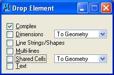
H.7.c. In the Drop Element dialog box, set Complex to on and set all other options to off.
H.7.d. Select and Accept the cell placed in Step H.3.
H.8. Copy Parallel all 5 arcs a distance of 18 feet to the northeast.
H.9. Working with the 5 arcs which were copied parallel in Step H.8 to create the divisional island triangle, (a) Extend/Shorten the western end of the eastern portion of the partially deleted line in Step H.4 to the northwestern edge of the 5 arcs, (b) Extend/Shorten the northwestern edge of the 5 arcs to the western end of the eastern portion of the partially deleted line in Step H.4, and (c) Extend/Shorten the southeastern edge of the 5 arcs to the rightmost lane edge of the right southbound lane of Road 2000 (a red line).
H.10. Set Active Level to Level 16.
H.11. Draw a line from the eastern end of the eastern portion of the partially deleted line in Step H.4 to the southeastern edge of the arcs extended/shortened in Step H.9 (c) with color of green (color=2), style of solid line (Style=0), and weight of 0 (weight=0).
H.12. Construct Circular Fillet with a radius of 3 feet and Truncate Both for all three points of the divisional island triangle.
H.13. Create a Complex Shape for the divisional island triangle.
H.13.a. From the MicroStation Main Tool menu, select the Groups palette (6th row left icon).
H.13.b. From the Groups palette, press the Create Complex Shape icon
(3rd icon from the left)  .
.
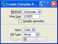
H.13.c. In the Create Complex Shape dialog box, set Method to Automatic, set Max Gap to 0.0001, set Simplify Geometry to unset, set Area to Solid, set Fill Type to None, and set Active Color to purple (color = 5).
H.13.d. Select and Accept in counterclockwise order the middle of the 5 arcs and the adjacent arc. The remaining elements for the complex shape will be automatically selected and a message "Shape closed" displayed at the bottom left of the MicroStation dialog box.
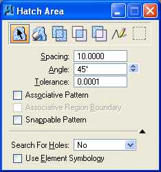
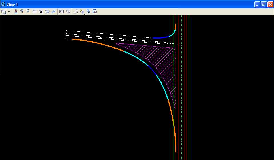
H.14. Hatch Area the complex shape using Element method, Spacing of 10, Angle of 45, Tolerance of 0.0001, Associative Pattern off, Snappable Pattern off, set Search For Holes to No, and Use Element Symbology off, and using the center of the edge of the northeast circular fillet as the pattern intersection point.
H.15. Set Active Level to Level 17.
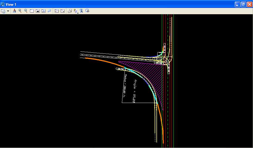
H.16. Choose cell RAMPRT for Placement. This cell is composed of a vehicle turn template for a WB-50 truck rotated for the eastbound Exit Ramp direction with a turn radius of 200 feet, a turn angle of 85 degrees, and a 2-foot clearance zone.
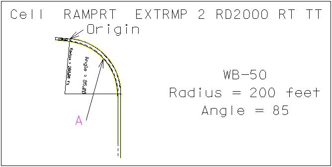
H.17. Place the Active Cell with an Active Angle of 0, X Scale of 1, Y Scale of 1, True Scale set on, and Relative set on such that Point A on the yellow clearance line of this cell is tangent to the critical point of the divisional island center arc according to the criteria in the top paragraph on page 592 of the 2004 AASHTO Green Book.
H.18. Review the clearance zones for the vehicle turn template and adjust the design of the eastbound Exit Ramp to southbound Road 2000 right turn if necessary.
H.19. Set Active Level to Level 1 and set Level Display for Level 17 to off.
I. Complete the design of the divisional island.
I.1. Draw a line perpendicular to the western end of the cell placed in Step H.3 at Point A to the northern edge of the Entrance Ramp.
I.2. Move Parallel the line drawn in Step I.1 a distance of 30 feet to the West.
I.3. Extend/Shorten all of the lines for the Entrance and Exit Ramp centerline and lane edges to the moved parallel line from Step I.2.
I.4. Delete the line drawn in Step I.1 and moved parallel in Step I.2.
J. Set Level Display for Level 11, Level 12, Level 14, and Level 17 to on.
K. Fit View 1 and plot the drawing using ENGR-SC2-Laser-2 and options for View 1, Monochrome, Letter, Landscape, Maximize, and Settings -> Print Attributes -> Fence boundary off and Print border on.
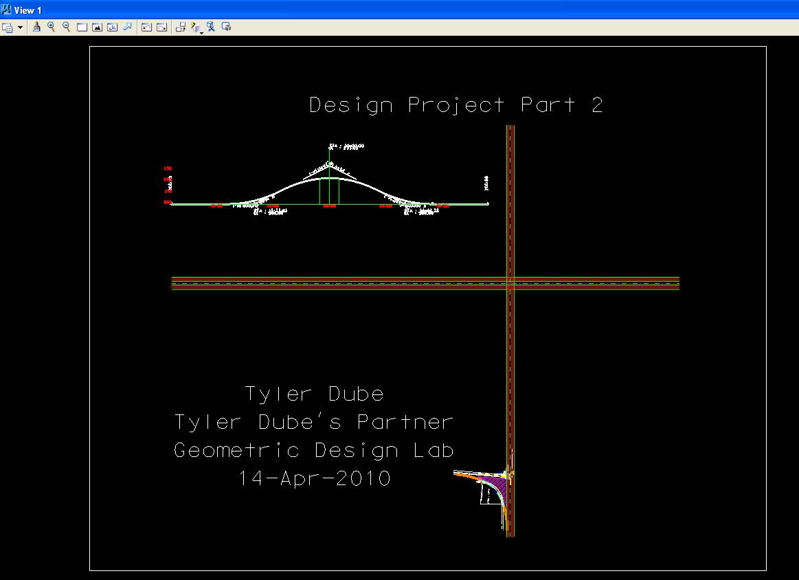
Design the Intersection Channelization of the Grade-Separated, Two-Quadrant, Partial Cloverleaf A Interchange using MicroStation Plot
L. Exit MicroStation.
M. Write the name of your team members on the plot.
N. Complete Design Project Design Questions section 2.
O. Reboot the computer.
Geometric Design Lab Spring 2011 web page
Latest Update: 11 Feb 2011 03:31 PM