Geometric Design Lab - Lab 12
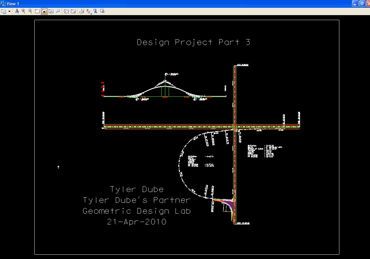
Design Project Part 3
Design the Freeway Entrance Ramp of the Grade-Separated, Two-Quadrant, Partial
Cloverleaf A Interchange using GEOPAK
Copyright © 2009 by Dr. Thomas W. Rioux
Students taking this course may print one copy of this document for their
personal class use.
Objective: Design the Freeway Entrance Ramp of the Grade-Separated,
Two-Quadrant, Partial Cloverleaf A Interchange using GEOPAK.
Activity: Start Windows Explorer and copy the file "Z:\MicroStation\job10.gpk" to "Z:\MicroStation\job12.gpk" and "Z:\MicroStation\lab_11.dgn" to "Z:\MicroStation\lab_12.dgn"; Start MicroStation and open the 2D design file "Z:\MicroStation\lab_12.dgn"; Start GEOPAK, set the standard GEOPAK user preferences for this class, and set the standard COGO preferences for this class; Open the GEOPAK Project named lab_12, set Job Number to 12, set Subject to "Design Project Part 3", and set Coordinate Geometry for Temporary Visualization; Store the points for the Freeway centerline, create a chain for the Freeway, and draw and station the Freeway chain; Draw and Station chain CHRD2000; Store the points for the Entrance Ramp centerline; Define the Entrance Ramp spiral and curve; Create a chain for the Entrance Ramp and draw and station the Entrance Ramp chain; Clear Visualized Elements (Temporary) and Exit COGO; Fit View 1 and plot the drawing; Exit MicroStation; Write the name of your team members on the plot; Complete Design Project Design Questions section 3; and Reboot the computer.
Background: This laboratory comprises Design Project Part 3 - Design the Freeway Entrance Ramp of the Grade-Separated, Two-Quadrant, Partial Cloverleaf A Interchange using GEOPAK (see Design Project). You will use the features of MicroStation and GEOPAK to design the horizontal alignment for the Entrance Ramp from Road 2000. For the design of the entrance ramp, see the TxDOT Design Division Operations and Procedures Manual 3/2009, Figure 3-35 (US) Entrance/Exit Ramps For One-Way Frontage Roads on page 3-90.
A. Start Windows Explorer and copy the file
"Z:\MicroStation\job10.gpk" to
"Z:\MicroStation\job12.gpk" and
"Z:\MicroStation\lab_11.dgn" to
"Z:\MicroStation\lab_12.dgn".
B. Start MicroStation and open the 2D design file "Z:\MicroStation\lab_12.dgn".
C. Start GEOPAK, set the standard GEOPAK user preferences for this class, and set the standard COGO preferences for this class.
D. Open the GEOPAK Project named lab_12, set Job Number to 12, set Subject to "Design Project Part 3", and set Coordinate Geometry for Temporary Visualization.
E. Store the points for the Freeway centerline, create a chain for the Freeway, and draw and station the Freeway chain.
E.1. Store the points for the Freeway centerline with Point 11 at the west end and Point 12 at the east end of the centerline (green dashed line). Calculate the station number for Point 11.
E.2. Store chain CHFRWY starting at the station number for Point 11 calculated in Step E.1 and using Point 11 and Point 12.
E.3. Set Active Level to Level 5.
E.4. Draw and Station chain CHFRWY using Label Scale of 200 and the settings from previous labs. Use MicroStation to visually verify the location of station 80+00 on the Freeway.
F. Draw and Station chain CHRD2000 using Label Scale of 200 and the settings from previous labs. Use MicroStation to visually verify the location of station 20+00 on Road 2000 (Point 21, Point 22, and Chain CHRD2000 were stored in Lab Assignment 10).
G. Store the points for the Entrance Ramp centerline.
G.1. Set Active Level to Level 2.
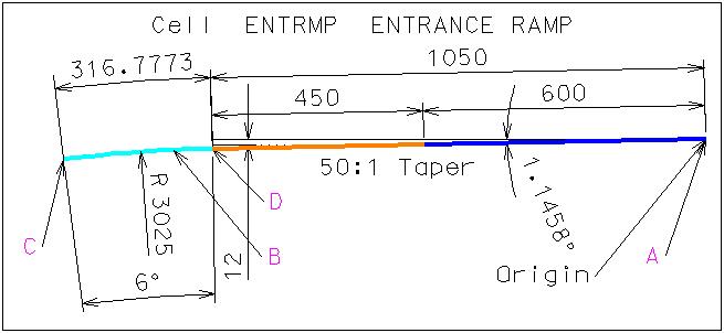
G.2. Choose cell ENTRMP for Placement. This cell is composed of a circular arc with 3025 foot radius and 6 degree sweep angle followed by a 1050 foot 50:1 tangent taper section. If desired, the sweep angle may be modified by dropping the complex cell for the entrance ramp and using the modify arc angle command. These values are derived from the Texas Department of Transportation Design Division Roadway Design Manual 3/2009 Table 2-3 Horizontal Curvature of High-Speed Highways and Connecting Roadways with Superelevation on page 2-12 and Figure 3-35 (US) Entrance/Exit Ramps For One-Way Frontage Roads on page 3-90. The information can also be found online at http://www.dot.state.tx.us then TxDOT Library then Online Manuals then Search then List all manuals alphabetically then Roadway Design Manual then 2 Basic Design Criteria then 4 Horizontal Alignment then Curve Radius and finally Table 2-3 and Roadway Design Manual then 3 New Location and Reconstruction (4R) Design Criteria then 6 Freeways then General Information and finally Figure 3-35 (US) Entrance/Exit Ramps For One-Way Frontage Roads.
G.3. Place the Active Cell with an Active Angle of 0, X Scale of 1, Y Scale of 1, True Scale set on, and Relative set on such that the east end (Point A) of the cell touches the right lane edge of the eastbound lanes of the Freeway (a red line) and the left portion of the cell (near Point B) is the desired distance from the centerline of the columns to the edge of the Entrance Ramp 14 foot ramp lane. If desired, the sweep angle may be modified by dropping the complex cell for the entrance ramp and using the modify arc angle command.
G.4. Using MicroStation, draw a 1500 foot line tangent to the west end of the entrance ramp arc (Point C).
G.5. Extend/Shorten the line drawn in Step G.4 to meet with the right lane edge of the Entrance Ramp created in Lab Assignment 11. This will be the PI for the entrance ramp curve.
G.6. Store Point 31 on the most northwest point on the right lane edge of the Entrance Ramp created in Lab Assignment 11 Step D.2 and Step I.3.
G.7. Store Point 32 at the intersection of the two lines intersected in Step G.5.
G.8. Store Point 33 at the west end of the arc of the entrance ramp cell placed in Step G.3 (Point C).
G.9. Store Point 34 at the east end of the arc of the entrance ramp cell placed in Step G.3 (Point D) (this point is also the west end of the 1050 foot 50:1 taper section line).
G.10. Store Point 35 at the east end of the taper section of the entrance ramp cell placed in Step G.3 (Point A).
H. Define the Entrance Ramp spiral and curve.
H.1. Determine the desired spiral length. Refer to Exhibit 3-30 on page 177, Spiral Curve Transitions on pages 184-185, and Length of Spiral on pages 185-191 in the 2004 AASHTO Green Book. Use the superelevation runoff calculated from Eqn 3-25 for the desired spiral length (HINT: pay careful attention to the # of lanes rotated). Round the desired spiral length to the next highest 0.1 feet if necessary.
H.2. Store a Spiral with Spiral Name of ENTR1, Type of SCS, Back Tangent with Point Back of 31 and PI Point of 32, Entry Length of the value from Step H.1, Radius of the value from Lab Assignment 11 Step C.1, Exit Length of the value from Step H.1, and Ahead Tangent with Point Ahead of 33.
H.3. Move the intersection and all cells placed in Lab Assignment 11 north or south to minimize the length of the tangent sections at Point 31 and at Point 33 being sure that the start of the spiral near Point 31 is to the west of or exactly at Point 31 and that the end of the spiral near Point 33 is to the west of or exactly at Point 33 (Hint: display only the graphics for the intersection drawn in Lab Assignment 11 including the vehicle turn templates, use the selection tool to fence the graphics, use Edit -> Group to group the graphics, then move the grouped graphics). An exact solution may be calculated; you may receive extra credit for calculating an exact solution and showing your calculations. With redefine set on, repeat Steps G.5, G.6, G.7, and H.2 as necessary until you have minimized the length of the tangent sections at Point 31 and Point 33. When completed, extend/shorten the right lane edge of the Entrance Ramp created in Lab Assignment 11 back to its original length from Lab Assignment 11.
H.4. Store a Curve By Endpoints with Name of ENTR2, PC Point Number of 33, PT Point Number of 34, Radius of 3025 feet, and Clockwise. This is the circular arc with 3025 foot radius and 6 degree sweep angle from the entrance ramp cell placed in Step G.3.
H.5. Set Level Display for Level 2 to off.
I. Create a chain for the Entrance Ramp and draw and station the Entrance Ramp chain.
I.1. Measure Length the centerline of the ramps drawn in Lab Assignment 11. Assuming that the ramps start at Station 0+00.00 at the intersection of the centerline of the ramps drawn in Lab Assignment 11 and the centerline of Road 2000, determine the station value for the centerline of the ramps at Point 31.
I.2. Store chain ENTRMP starting at Station value determined in Step I.1 and using Point 31, Spiral ENTR1B, Curve ENTR1, Spiral ENTR1A, Curve ENTR2, and Point 35.
I.3. Draw and Station chain ENTRMP using Label Scale of 200 and the settings from previous labs.
I.4. Move the curve data and the station data so that it is visible.
J. Clear Visualized Elements (Temporary) and Exit COGO.
K. Fit View 1 and plot the drawing using ENGR-SC2-Laser-2 and options for View 1, Monochrome, Letter, Landscape, Maximize, and Settings -> Print Attributes -> Fence boundary off and Print border on.
Design the Freeway Entrance Ramp of the Grade-Separated, Two-Quadrant, Partial Cloverleaf A Interchange using GEOPAK
L. Exit MicroStation.
M. Write the name of your team members on the plot.
N. Complete Design Project Design Questions section 3.
O. Reboot the computer.
Geometric Design Lab Spring 2011 web page
Latest Update: 11 Feb 2011 03:31 PM