 ;
and finally press the Generate Superelevation Transitions push button.
;
and finally press the Generate Superelevation Transitions push button.Geometric Design Lab - Lab 14
Design Project Part 5
Define the Superelevation and
Complete the Design of the Grade-Separated, Two-Quadrant,
Partial Cloverleaf A Interchange using GEOPAK
Copyright © 2009 by Dr. Thomas W. Rioux
Students taking this course may print one copy of this document for their personal class
use.
Objective: Define the Superelevation and Complete
the Design of the Grade-Separated, Two-Quadrant, Partial Cloverleaf A Interchange
using GEOPAK.
Activity: Start Windows Explorer and copy the file "Z:\MicroStation\job13.gpk" to "Z:\MicroStation\job14.gpk" and "Z:\MicroStation\lab_13.dgn" to "Z:\MicroStation\lab_14.dgn"; Start MicroStation and open the 2D design file "Z:\MicroStation\lab_14.dgn"; Start GEOPAK, set the standard GEOPAK user preferences for this class, and set the standard COGO preferences for this class; Open the GEOPAK Project named lab_14, set Job Number to 14, set Subject to "Design Project Part 5", and set Coordinate Geometry for Temporary Visualization; Define the vertical profile for the Entrance Ramp; Define the vertical profile for the Exit Ramp; Define the superelevation for the Entrance Ramp; Define the superelevation for the Exit Ramp; Clear Visualized Elements (Temporary) and Exit COGO; Change the level of all lines and arcs used for construction to Level 2 and turn Level 2 viewing off for all views; Attach the TxDOT Plan Sheet file "Z:\MicroStation\design_project_plan_sheet.dgn" to "Z:\MicroStation\lab_14.dgn" as a reference file; Create a Saved View and attach "Z:\MicroStation\lab_14.dgn" as a reference file to itself using the saved view; Plot the drawing; Exit MicroStation; E-mail "Z:\MicroStation\lab_14.dgn" to Instructor Dr. Kara Kockelman at by the lab assignment due date and time; and Complete Design Project Design Questions section 5; and Reboot the computer.
Background: This laboratory comprises Design Project Part 5 - Define the Superelevation and Complete the design of the Grade-Separated, Two-Quadrant, Partial Cloverleaf A Interchange using GEOPAK (see Design Project). You will use the features of MicroStation and GEOPAK to complete the design.
A. Start Windows Explorer and copy the file "Z:\MicroStation\job13.gpk" to "Z:\MicroStation\job14.gpk" and "Z:\MicroStation\lab_13.dgn" to "Z:\MicroStation\lab_14.dgn".
B. Start MicroStation and open the 2D design file "Z:\MicroStation\lab_14.dgn".
C. Start GEOPAK, set the standard GEOPAK user preferences for this class, and set the standard COGO preferences for this class.
D. Open the GEOPAK Project named lab_14, set Job Number to 14, set Subject to "Design Project Part 5", and set Coordinate Geometry for Temporary Visualization.
E. Define the vertical profile for the Entrance Ramp starting at the beginning station for the Entrance Ramp (Point 31), ending at the ending station for the Entrance Ramp (Point 35), using a Reference Elevation of 200.0 and horizontal from beginning to end. Save Profile As setting Profile to PROFENRMP and setting File to j14o<your_2_initials>enrp.inp. If there was an error saving the vertical profile, in the Coordinate Geometry Job:14 Operator: <your_2_initials> dialog box in the COGO Key-in field, enter make input file j14o<your_2_initials>enrp.inp pro PROFENRMP and press the Enter key.
F. Define the vertical profile for the Exit Ramp starting at the beginning station for the Exit Ramp (Point 41), ending at the ending station for the Exit Ramp (Point 45), using a Reference Elevation of 200.0, and horizontal from beginning to end. Save Profile As setting Profile to PROFEXRMP and setting File to j14o<your_2_initials>exrp.inp. If there was an error saving the vertical profile, in the Coordinate Geometry Job:14 Operator: <your_2_initials> dialog box in the COGO Key-in field, enter make input file j14o<your_2_initials>exrp.inp pro PROFEXRMP and press the Enter key.
G. Define the superelevation for the Entrance Ramp.
G.1. In the Automated Superelevation dialog box, choose File -> Preferences and ensure that the preferences are set according to Lab Assignment 07 Step J.
G.2. In the Automated Superelevation dialog box, set Job to 14, set Design Speed to the design speed for the ramp, set Preference File to txdot_uc, set e Selection to 8% e max, set Chain to ENTRMP, set Begin to the beginning station for the ramp, set End to the ending station for the ramp (NOTE: this may have to be set to 0.01 less than the POT value to avoid rounding issues in GEOPAK), set Facility to Undivided, set L Selection to all cases, and set Create Input File to super14entrmp.inp.
G.3. In the
Automated Superelevation dialog box, press the Left tab and set Profile to
PROFENRMP, set Tie to
Offset, set Offset to 0.0000, set %
Slope to 2.0000, set 1st Offset to -14.0000, set 2nd
Offset to 0.0000, set Dependent to checked;
press the Right tab and set Profile to
PROFENRMP, set Tie to
Offset, set Offset to 0.0000, select the
lane entry (if any), delete the lane entry by pressing the delete push button
;
and finally press the Generate Superelevation Transitions push button.
G.4. In the Text Editor: super14entrmp.inp dialog box, edit the filler line station/slope entries to assure the following and Save:
beginning POT +2.0 % normal crown beginning Spiral ENTR1B +2.0 % normal crown ending Spiral ENTR1B +8.0 % full superelevation beginning Spiral ENTR1A +8.0 % full superelevation ending Spiral ENTR1A +2.0 % normal crown 2/3 length before beginning Curve ENTR2 +2.0 % normal crown 1/3 length after beginning Curve ENTR2 +3.7 % superelevation 1/3 length before ending Curve ENTR2 +3.7 % superelevation 2/3 length after ending Curve ENTR2 +2.0 % normal crown ending POT +2.0 % normal crown
G.5. In the Superelevation Autoshape Builder dialog box, set Autoshape Input File to Z:\MicroStation\super14entrmp.inp, deselect Display Only, deselect Override Input File Level Symbology, press the Draw Superelevation Shapes push button, and close the Superelevation Autoshape Builder dialog box. Inspect the superelevation shapes with View Attributes of Fill set to Off.
H. Define the superelevation for the Exit Ramp.
H.1. In the Automated Superelevation dialog box, set Job to 14, set Design Speed to the design speed for the ramp, set Preference File to txdot_uc, set e Selection to 8% e max, set Chain to EXTRMP, set Begin to the beginning station for the ramp, set End to the ending station for the ramp (NOTE: this may have to be set to 0.01 less than the POT value to avoid rounding issues in GEOPAK), set Facility to Undivided, set L Selection to all cases, and set Create Input File to super14extrmp.inp.
H.2. In the
Automated Superelevation dialog box, press the Left tab and set Profile to
PROFEXRMP, set Tie to
Offset, set Offset to 0.0000, set %
Slope to 2.0000, set 1st Offset to 0.0000, set 2nd
Offset to 14.0000, set Dependent to checked;
press the Right tab and set Profile to
PROFEXRMP, set Tie to
Offset, set Offset to 0.0000, select the
lane entry (if any), delete the lane entry by pressing the delete push button
;
and finally press the Generate Superelevation Transitions push button.
H.3. In the Text Editor: super14extrmp.inp dialog box, edit the filler line station/slope entries to assure the following and Save:
beginning POT +2.0 % normal crown beginning Spiral EXTR1B +2.0 % normal crown ending Spiral EXTR1B -8.0 % full superelevation beginning Spiral EXTR1A -8.0 % full superelevation ending Spiral EXTR1A +2.0 % normal crown (may not be listed) beginning Spiral EXTR2B +2.0 % normal crown (may not be listed) ending Spiral EXTR2B +8.0 % full superelevation beginning Spiral EXTR2A +8.0 % full superelevation ending Spiral EXTR2A +2.0 % normal crown 2/3 length before beginning Curve EXTR3 +2.0 % normal crown 1/3 length after beginning Curve EXTR3 +3.7 % superelevation length before ending Curve EXTR3 +3.7 % superelevation ending POT +2.0 % normal crown
H.4. In the Superelevation Autoshape Builder dialog box, set Autoshape Input File to Z:\MicroStation\super14extrmp.inp, deselect Display Only, deselect Override Input File Level Symbology, press the Draw Superelevation Shapes push button, and close the Superelevation Autoshape Builder dialog box. Inspect the superelevation shapes with View Attributes of Fill set to Off.
I. Clear Visualized Elements (Temporary) and Exit COGO.
J. Change the level of all lines and arcs used for construction to Level 2 and turn Level 2 viewing off for all views.
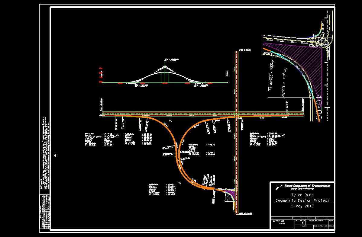
K. Attach the TxDOT Plan Sheet file "Z:\MicroStation\design_project_plan_sheet.dgn" to "Z:\MicroStation\lab_14.dgn" as a reference file using Attachment Mode of Interactive, with Orientation set to Coincident, Scale (Master:Ref) of 1800:1, and True scale checked. Fit All and use Tools -> Move to move the reference file so that all elements of the design are within the plan sheet.
L. Create a Saved View and attach "Z:\MicroStation\lab_14.dgn" as a reference file to itself using the saved view.
L.1. Set Level Display for Level 11, Level 12, Level 14, and Level 17 to on and Level 13 to off.
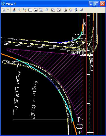
L.2. Fit View 1, Window Area in View 1, and adjust the size of View 1 such that the Station 36+00 through 40+00 tick marks and the WB-50 truck turn templates are visible.
L.3. Choose Utilities -> Saved Views.
L.4. In the Saved Views dialog box,
press the Save View icon
 , set
View to 1, set Name to TRUCKS, set Description
to Truck Turn Templates, press the
OK push
button, and close the Saved Views dialog box.
, set
View to 1, set Name to TRUCKS, set Description
to Truck Turn Templates, press the
OK push
button, and close the Saved Views dialog box.
L.5. Set Level Display for Level 11, Level 12, Level 14, and Level 17 to off and Fit View 1.
L.6. Attach the file "Z:\MicroStation\lab_14.dgn" to "Z:\MicroStation\lab_14.dgn" as a reference file with Attach Method of Interactive, with Orientation set to Saved Views TRUCKS, Scale (Master:Ref) of 5:1, and True scale checked. Fit All and use Tools -> Move to move the reference file so that all elements of the design are within the plan sheet.
M. Plot the drawing.
M.1. Set View Attributes Data Fields and Fill to off.
M.2. Place the title "Geometric Design Lab Spring 2011", "Design Project", your names, and the assignment due date of 05-May-2010 in the box labeled Texas Department of Transportation in the lower right box of the plan sheet using a text height, text width, and text spacing of 50 feet with font of 3 (font=ENGINEERING), justification of Center Center, level of Level 1 (level=Level 1), color of white (color=0), style of solid (style=0), and weight of 0 (weight=0).
M.3. Place a fence from the outside plan sheet rectangle and plot the drawing using \146.6.89.61LRC_Plotter and options for Fence, True color, Paper Size of ANSI E, landscape, a scale of 170 ft / in, and Settings -> Print Attributes -> Fence boundary off and Print border on. To add the printer, go to Printers and Faxes, select Add a Printer, press Next, press Next again, and type \\146.6.89.30\CAEE-Color_Plotter into the Connect to this Printer field. Do not fold the plot.
Define the Superelevation and Complete the Design of the Grade-Separated, Two-Quadrant, Partial Cloverleaf A Interchange using GEOPAK
N. Exit MicroStation.
O. E-mail "Z:\MicroStation\lab_14.dgn" to Instructor Dr. Kara Kockelman at by the lab assignment due date and time.
P. Complete Design Project Design Questions section 5.
Q. Reboot the computer.
Geometric Design Lab Spring 2011 web page
Latest Update: 11 Feb 2011 02:40 PM